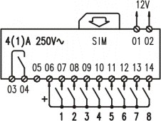
CONTROLLING THE APPLIANCE OR PROCESS

Connect the contact on the supply line of the load to be controlled.
Alerts can be issued to predefined recipients (up to 100) when input status changes from open to close and/or vice-versa
Features of the GSM Alarm
Output Power
• Class 4 (2W @ 900 MHz)
• Class 1 (1W @ 1800 MHz)
Power Supply
• 12 VDC ±20% polarity independent
• 12 VAC ±20%
• < 30 mA @ 12 VDC in standby mode
• < 100 mA @ 12 VDC in standby mode, relay on
• < 200 mA @ 12 VDC in communication mode
• < 1 A @ 12 VDC max peak current
• Optional NiMH backup battery
Inputs
• SPST contact, 2,5mmq (AWG14) screw terminals
• voltage < 20V (internal)
• current < 2 mA
Output
• SPST contact , 2,5mmq (AWG14) screw terminals
• rated current 4 A
• rated voltage 250 Vac
• max breaking capacity 2500 VA
• min contact load 100 mA / 12V
• insulation 250 V (IEC60644/VDE0110b-cat.III/C)
Data Interface
• RS-232 (RJ45, internal)
• 300...115200 BIT/s
• 7/8 data bit, 1/2 stop bit, 1 parity bit
• Software handshake , Hardware handshake
Control
• SMS multiple commands, case insensitive
• SMS timer and schedule commands
• CLIP (pulse mode)
• CLIP (toggle mode)
Reports / Alarms
• SMS, Status SMS (specific for each recipient)
• FAX (specific for each recipient)
• Free Call
Special Features
• Power fail detection (blackout)
• Local and remote configuration
• Log tracing to com port
• Real time clock (autosync)
• Scheduled events
• Users management and Interactive messages
• Configurale inputs debounce time
Users
• up to 250 users (SIM card phonebook)
• up to 250 advanced users
• up to 100 supervisors
• up to 100 recipients |


